
Pipeline
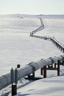
Pipeline
Long series of Pipes usually of large diameter often underground with few fittings & equipment’s mostly Pumps & Valves mainly to control the flow, that are laid with an intention to transport any fluid whether liquid or gas over long distances.
- The design of pipeline is governed by ASME B31.4 that is code for Liquid Transportation Systems for Hydrocarbons, Liquid Petroleum Gas, Anhydrous Ammonia, and Alcohol and ASME B31.8 that is a code for Gas Transmission and Distribution Piping Systems.
- The constructions drawing here are termed as alignment sheet.
- Pipeline design generally involves river crossing, highway crossing, rail line crossing etc.
- The pipeline is Series of straight pipe welded together over a long distance.
- The pipeline can run underground, aboveground and underwater such as a subsea pipeline.
- Pipelines are mostly large diameter that transport bulk liquid or gas from one place to other sometimes 1000s of miles in distance.
- In pipeline few equipment are used within the Pipeline system such as pumps, valves & instruments that support the function of the system to transport fluid safely over a long distance.
Piping

Piping
Large series & networks of Pipes within the well-defined boundaries of the plant/plot with all fittings & equipment’s like Pump, Valves, Unions & other Miscellaneous items with an intention to transfer fluid from one facility to another within those boundaries as required.
- Piping is designed in accordance with ASME B31.3 that is Process Piping code and for power plant piping ASME B31.1 that is code for Power Piping.
- The construction drawings here are termed as isometric drawings.
- Piping is a Complex network of pipe & fittings within the defined boundaries of the plant.
- Piping is mostly above ground with very few underground services.
- Piping can be from ½” to 80” as per the plant design requirements that transfer fluid from on equipment to another within the plant boundary.
- Variety of equipment such as a pump, valves, filter vessel, column, heat exchanger, instruments are used within the piping system that supports the function of the plant to produce finish product.
Onshore System
| SL. NO. | Onshore PIPELINE | Onshore PIPING | |
| 1 | Design Codes | ||
| · ASME B31.4 : Pipeline Transportation Systems for Liquids and Slurries · ASME B31.8 : Gas Transmission and Distribution Piping Systems | · ASME B31.3 : Process Piping | ||
| 2 | Scope | ||
| Outside plant boundary Cross-country (i.e. villages, fields, river, canal, railway, highway, cities, deserts, forests, hills, Ghats etc.) | Within plant boundary (up to all nozzles/ equipment terminal points) | ||
| 3 | Type of pipe | ||
| Line pipes as per following code: · API Spec 5L: Specification for Line pipes | Assorted pipes as per following code: · ASTMs · BS · API 5L | ||
| 4 | Valves | ||
| Valves are procured as per following code: · API 6D: Specification for Pipeline and Piping Valves Full Bore (FB) Ball Valves are used for smooth passage of pigs. | Valves are procured as per following code: · BS · API Standard Full bore (FB) and Reduced bore (RB) both types of valves are used as per respective valve standards. There is no requirement for pigging. | ||
| 5 | Welding | ||
| Welding code: · API Std. 1104: Welding of Pipelines and Related Facilities Type of welding: | Welding code: · ASME Sec. IX: Standard for Welding and Brazing Procedures, Welders, Brazers and Welding and Brazing Operators Type of welding: | ||
| 6 | Weld joint inspection (NDT requirements) | ||
| 100% by Automatic UT or RT (by using X-Ray) | 5% to 100% (mostly by using gamma ray source) | ||
| 7 | Analyses | ||
| – Wall Thickness Analysis – Elastic Bend Radius Analysis – Stability Analysis for Water Bodies/ Marshy Areas – Horizontal directional drilling design analysis – Railroad/ Highway Crossing Analysis – Casing Pipe Analysis for Crossings – Seismic Analysis | – Piping wall thickness calculation [as input to Piping Material Specification (PMS)]
– Piping Stress Analysis (by Caesar II). Following analyses are performed on CAESAR II· Static Analysis· Dynamic Analysis · Wind Analysis · Flange Leakage Analysis · Seismic Analysis | ||
| 8 | Installation | ||
| Buried (mostly) | Above ground/ On rack/ slippers/ T-postal etc. | ||
| 9 | Special Installations | ||
| Across rivers · Horizontal Directional Drilling (HDD) method · Micro-tunneling method Across road/ rail/ highway · Auger boring/ jacking boring method · Shallow HDD Ghats/ Hills – Special equipment used | Special fabrication methods: · Modular installations · Finning · Studding · Jacketing · Spooling inside warehouse · U/G piping for cooling water | ||
| 10 | Special Equipments | ||
| · Sectionalizing Valves (Remote operated) · Insulating Joints · Scraper Launcher/ Receiver · Stem Extended Valves (for buried valves) · Flow Tee · Long Radius bends (R=6D) · Cold field bends (R = 30D or 40D) | · Expansion Joints · Motor Operator Valves (MOV) · Cryogenic Valves · Springs | ||
| 11 | Survey | ||
| · Topographical Survey (all along the pipeline route) · Geotechnical investigation (all along the pipeline route) · Soil resistivity survey (all along the pipeline route) · Hydrological Survey for water bodies (for scour depth calculation) · Cadastral Survey (for RoU acquisition) | · Wind profile from meteorology · Seismic study of plot | ||
| 12 | Corrosion Protection Coating | ||
| · Three Layer Polyethylene (3LPE) coating · Three Layer Polypropylene (3LPP) coating · Fusion bonded epoxy (FBE) coating · Coal tar enamel (CTE) Coating | · Painting | ||
| 13 | Cathodic Protection System | ||
| · Impressed Current Cathodic Protection (ICCP) system · Sacrificial Anode (limited locations) | · Not applicable | ||
| 14 | Hydrostatic testing | ||
| Gauge Plate run of 95% of ID of highest thickness of pipes Test Pressure · 1.25 times of Design Pressure (for liquid pipelines) · 1.25 to 1.5 times of Design Pressure (for gas pipelines) Maximum: · Pressure equivalent to Hoop stress of 95% of SMYS of pipe material Hold period: 24 hours (generally) Selection of hydrostatic test section based on elevation difference of ground profile | No gauge plate run is done. Generally card-board blasting is done to clean the piping. Test Pressure · 1.5 × Design Pressure × Temperature Factor Maximum: · based on line schedule Hold period: 2 – 6 hours | ||
| 15 | Preservation | ||
| Preservation of pipeline with corrosion inhibited water or by filling of inert gas (N2) | Not applicable | ||
| 16 | Communication System | ||
| Telecom/ SCADA | Not applicable | ||
| 17 | Pigging | ||
| Intelligent Pigging | Not applicable | ||
| 18 | Machines/ Equipments required for installation | ||
| · Trencher · Backhoe/ Excavator · Side Boom · Cold field bending machine · Holiday Detection Machines · Pneumatic/ Hydraulic Internal Clamps | |||
Offshore System
| SL. NO. | Offshore PIPELINE | Offshore PIPING | |
| 1 | Design Codes | ||
| · DNVGL-ST-F101 : Submarine pipeline systems · API RP 1111 : Design, Construction, Operation and Maintenance of Offshore Hydrocarbon Pipelines (Limit state design) | · ASME B31.3 : Process Piping | ||
| 2 | Installation | ||
| Subsea (in water on seabed or buried in seabed) | Deck Platform Piping (similar to plant) | ||
| 3 | Survey (Subsea) | ||
| · Geophysical survey/ Bathymetric Survey by using side scan sonar, sub-bottom profiler and echo-sounder · Met-Ocean data collection · Geo-technical data of the pipeline route | Not Applicable | ||
| 4 | Pipes | ||
| Line pipes are utilized as per following specs: · API Spec 5L : Specification for Line pipes · DNVGL-ST-F101 : Submarine Pipeline Systems | Assorted Pipes are utilized as per following specs: · ASTM Standards | ||
| 5 | Valves | ||
| Full bore Valves for smooth passage of intelligent pigs are utilized as per spec: · API 6D SS : Specification on Subsea Pipeline Valves | Reduced bore valves are utilized (as there is no requirement for pigging) as per spec: · BS/API standards | ||
| 6 | Analyses | ||
| · Wall thickness Analysis · On-bottom Stability · Span Analysis · Global Buckling – Lateral and Upheaval · Pipeline Expansion Analysis · Riser Design (Span , Stress & Flexibility Analysis) · Riser Clamp Design · Pipeline Crossing Design and Analysis · Installation Analyses such as :- Pipelay Analyses in OFFPIPE, Shore approach installation design & Analyses, Riser/ Expansion Spool installation analyses, Hoses lifting & installation analyses | · Deck piping stress analysis using CAESAR II | ||
| 7 | Environmental Loads (Met-ocean Parameters) | ||
| Wave, current and external pressure and buoyancy | Wind load | ||
| 8 | Corrosion Protection Coating | ||
| Coatings such as:– · Coal Tar Enamel Coating (CTE) · Three layer polyethylene coating (3LPE) · Three layer poly-propylene coating (3LPP) · Double layer fusion bonded epoxy coating (DLFBE) | Painting | ||
| 9 | Cathodic Protection System | ||
| Sacrificial Anodic Cathodic Protection (SACP) system | Not Applicable | ||
| 10 | Welding | ||
| Welding is performed as per specification: · API Std. 1104 : Welding of Pipelines and Related Facilities Mostly automatic welding on pipelay barge. | Welding is performed as per specification: · ASME Sec. IX : Standard for Welding and Brazing Procedures, Welders, Brazers and Welding and Brazing Operators Manual welding at fabrication yard. | ||
| 11 | Weld joint inspection (NDT requirements) | ||
| 100% by Automatic UT | Mostly by using gamma ray source. | ||
| 12 | Special Equipments | ||
| · Subsea Isolation Valve (SSIV) · LR Bends · Flow tee · Pipeline End Manifold (PLEM) · Single Point Mooring (SPM) system · Submarine hoses · Floating hoses · Cables and umbilical installation · Piggy-back pipelines | Not Applicable | ||
| 13 | Installation Equipment | ||
| · Pipelay Barge · Derrick Barge · Diving support vessel · Dynamic Positioning (DP) barge (for deep-water) | · Pre-fabricated deck piping | ||
| 14 | Installation Methods | ||
| · S-lay Method (for shallow water installation) · J-Lay Method (for deep water installation) · Shore pull/ barge pull near Land Fall Point (LFP) | · Along with deck structure | ||
| 15 | Hydrostatic testing | ||
| Gauge Plate run of 95% of ID of highest thickness of pipeline. Test Pressure· Minimum : 1.25 times x Design PressureHold period · 24 hours | No gauging is done. Test Pressure· Maximum : As per line scheduleHold period · 2 hours | ||
| 16 | NDT requirements | ||
| 100% weld joints by RT or AUT | Varies from 10% to 100% depending upon service. | ||
| 17 | Intelligent Pigging | ||
| Compliant | Not applicable | ||
[Table source: – From Web]
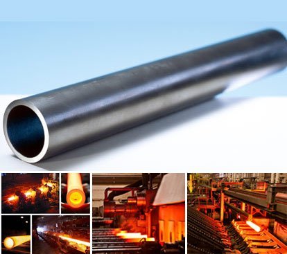
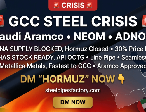
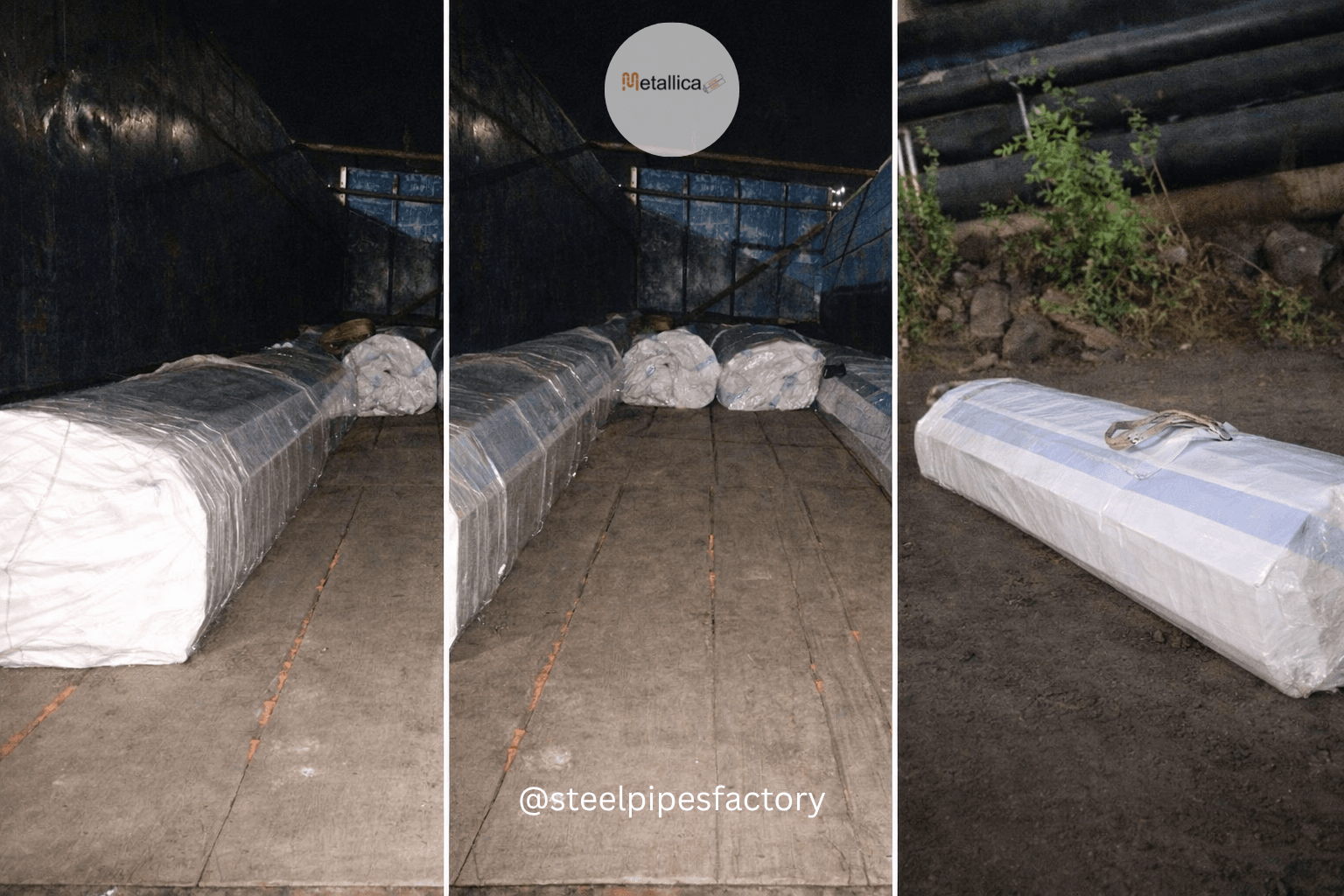
Metallica is one of the oldest importers, and big steel seller and stockholder in India, its customers range from procurement managers to traders or resellers in almost every corner of India and overseas.
We procure significant quantities of materials from Indian carbon steel pipe mills and overseas manufacturers of stainless steel pipes. Given our extensive network for sourcing the best quality goods at most competitive prices, we are a preferred seller of steel products for various turnkey project in India and Worldwide.
Our annual sales volume over 70,000 tonnes in India and Worldwide, has won us the dealership and distributorship of renowned seamless (JINDAL, ISMT) and welded steel pipes manufacturing companies across the globe. Contact us now!
Leave A Comment